
Improvement of Water Supply Automatic Regulation System
Rotary activation furnace is an internally heated fluidized bed continuous production activation furnace. The activator is water vapor and flue gas. This method is also used in the production of wood charcoal.
If you have any questions, please contact with us directly. Welcome you can visit our Factory.For inqury,Please send mail directly to us. Rotary Activated Stove,Activated Carbon Activation Furnace,Activated Carbon Production Machine,Activated Carbon Processing Equipment Shandong Hengyi kaifeng Machinery Co.,Ltd , http://www.xhykf.com
I. Current situation analysis Adjust valve characteristics poor (1) valve leakage is large, so adjust the door always adjust between 30% to 60%.
(2) The characteristic curve of the valve is poor, and the rate of change of flow rate varies, resulting in a large variation.
In this way, on the one hand, the system caused a large disturbance, such as water level fluctuations, pressure fluctuations to the jellyfish, etc., which caused frequent mechanical action of the adjustment mechanism, serious mechanical wear, severe motor burn, and direct threat to safety production.
2. The uneconomic operation of the feedwater pump is required to ensure that the water supply valve can timely adjust the steam drum water level adjustment within a given allowable range. The pressure of the jellyfish pipe is usually maintained at about 17 MPa so as to form a sufficient door-to-door differential pressure; the feed water pump often operates at Above 5300r/min (the maximum speed of the feed pump is 6000r/min); the feedwater pump current is above 420A; causing the feedwater pump to run for a long time near full load, and the speed control pump operates as a fixed speed pump. This mode of operation is neither safe nor economical.
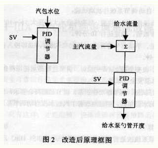
Second, the system transformation 1. Renovation plan 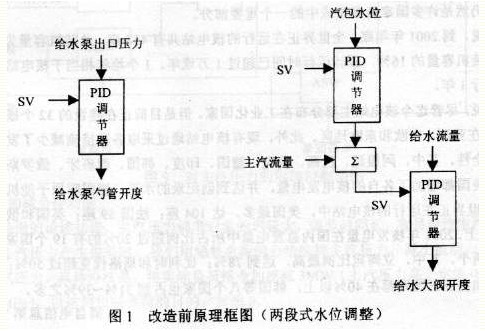
2. Configure the system according to the transformation plan and the design of the adjustment system configuration diagram. (1) Ladder diagram: Implement the logic control in the system.
(2) Function Block Diagram: Realize the adjustment control in the system.
(3) Database: Provides information for the system.
(4) Graphic: Provides a graphical monitoring and operation interface for the system to realize human-machine exchange.
3. Electrical Pump Control Circuit Inspection Test and Troubleshooting 3. Operation Test Debugging System Configuration and Control Circuit Inspection After the test is completed, the thermal automatic adjustment system and equipment have the conditions for automatic investment. From the thermal workshop, a "test procedure" is formulated. The operation department formulates "safety measures". The livelihood department, thermal workshop, and operation department form a test group, and the feed water pump is put into an automatic closed-loop test.
(1) Cut off the water supply valve automatically and burn it automatically. Do the following tests:
â— Test water supply, steam, water level, drum pressure, main steam pressure signal protection;
â— check the direction of action of the regulator;
â— Initially set the regulator parameter value.
(2) The combustion input is automatic and the large feedwater valve is automatically put into operation.
(3) When the boiler load is stable and the drum water level is stable at normal value and the operation is normal, the large water supply valve will be automatically cut off and the feed water pump spoon will be automatically put into use. Observe the action of the regulator, gradually modify the parameters of the regulator, observe the effect until the regulator is in normal operation, and the adjustment system is stable. Then, run for about ten minutes.
(4) Perturbation test for automatic adjustment system of feedwater pump scoop:
â— Gradually operate the large feedwater valve to a wide open position. Open the large feedwater valve by 5% to 10% each time. Observe the action of the feedwater scoop regulator, set the parameter values, and run stably for 10 minutes.
â— Do scoop disturbance test. Manually change the opening of the scoop tube by 10% to 20%, immediately put it into automatic, observe the action of the regulator, and run it for 10 minutes.
â— Load disturbance test. Change the load 2MW ~ 3MW, adjust the process quality indicators meet the requirements.
(5) Safety tests for various load feed pumps.
After two weeks of closed-loop operation tests, the regulators operated normally, and the quality of the regulators complied with the requirements. All the parameters of the feedwater pumps were normal, and the unit consumption of the feedwater pumps was effectively reduced. The automatic adjustment of the water level of the drum was significantly improved, and the boiler operation was improved. Stability and economy.
IV. Estimate of Economic Benefits 1. The main parameters before and after the transformation of the water supply automatic regulation system before and after the transformation of the water supply regulation system are shown in Table 1. 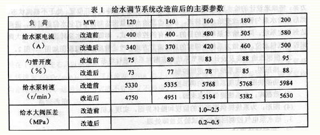
Our factory load distribution is as follows:
From 8:00 to 12:00, the load is 120 to 200MW, and the current reduction is calculated as 30A.
From 12:00 to 18:00, the load is 120-150MW, and the reduced current is calculated as 50A:
The load is 150-200MW from 18:00 to 22:00, and the reduction current is calculated as 30A:
From 22:00 to 8:00, the load is 120 to 150 MW, and the current is reduced by 50 A.
According to the calculation of 0,12 yuan per kilowatt hour, it can be estimated that 4 million kilowatts of electricity will be saved each year, and 480,000 yuan will be saved.
