Intelligent power supply and distribution design for an international airport terminal
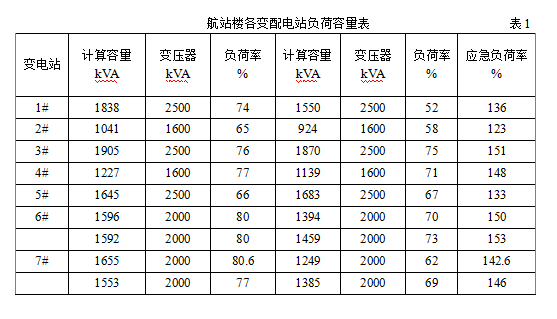
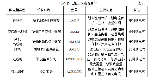
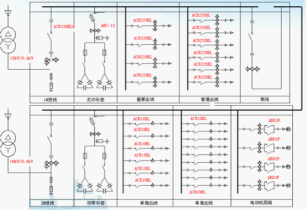
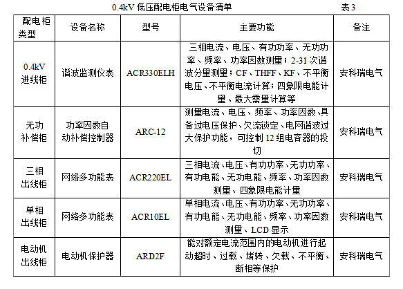
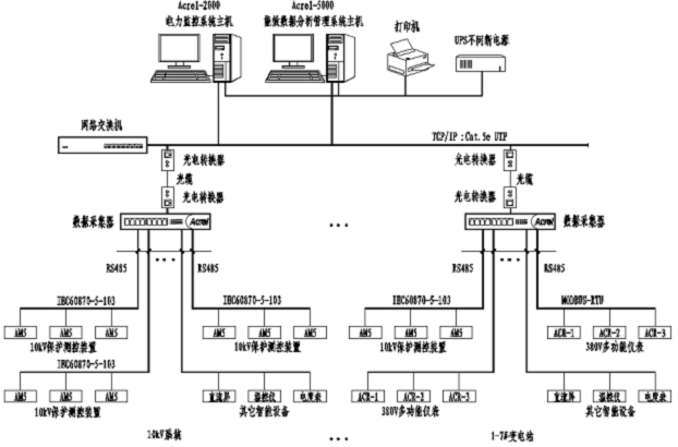
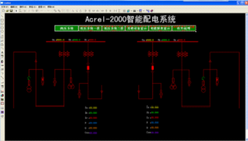
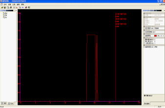
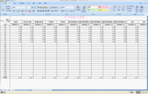
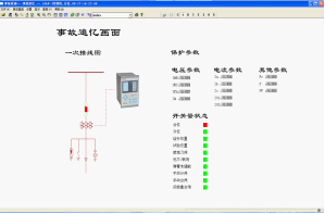
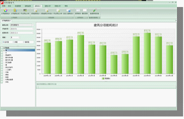
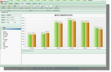
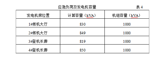
Ankerui Qingqing Jiangsu Ankerui Electric Appliance Manufacturing Co., Ltd. Jiangyin, Jiangsu 214405 1 Project Status and Distribution Station Distribution The international airport is powered by a local 220kV substation, and has a total of three independent 35kV power supplies. It is introduced into the airport's 1# and 2# total pressure-relief stations, and after stepping down to 10kV, it is distributed to various power distribution stations within the airport. The length of the boarding corridor at the airport terminal is 1370m, and the building area of ​​the terminal hall and the boarding gallery is more than 50,000m 2 per floor . In order to make the power supply in-depth load center, reduce power consumption, improve power quality, save investment costs, after comprehensive consideration, the power distribution station adopts the following layout: Set up two independent power distribution stations in the basement floor of the waiting hall, the main power supply The electricity load for all terminal halls; a total of 5 substations at the bottom of the boarding corridor to provide power to the connection corridors of the boarding corridors and terminals. The load and capacity of the 7 substations in the terminal building are shown in Table 1. The total electricity load in the terminal building is about 34,679 kVA, of which the active computing capacity is 26,703 kVA. As can be seen from Table 1, the seven power distribution stations share 18 transformers, of which 6 are 2500 kVA, 8 are 2000 kVA, and 4 are 1600 kVA. In the substation, manual/automatic bus-coupler switches are installed on the low-voltage side of each 380V/220V transformer. When one of the transformers fails, the other transformer will assume a 133% load of the transformer's rated capacity for a long period of time after the strong wind has cooled down to reduce power outages due to transformer failure. 2 Transformer Distribution System Design Each power distribution station in the terminal building is powered by two independent 10kV power supplies led from the main step-down station of the airport. The two power supplies are usually powered at the same time, and are used as backups in case of failure. The 10kV high-voltage side of the power supply system adopts a single-bus segment, with a manual/automatic bus-coupler switch in the middle. When there is a fault in one of the two power supply lines, the other load will be used for all the distribution transformers in the station, and the standby rate at the 10kV side is 100%. The system wiring of the seven substations is the same in principle. The difference is only the number, capacity and outlet circuit of the transformer. Four transformers are installed in each of the two substations in the terminal hall, with the same capacity. Each line is usually powered by one 10kV power supply for both transformers. After one 10kV power supply fails, the other 10kV power supply bears all four. Transformer capacity load. The 10kV distribution system diagram is shown in Figure 1. 2.1 10kV Distribution Cabinet The 10kV power distribution cabinet adopts a withdrawable, fully-enclosed, and mid-slide structure. The cabinet body has a reliable “five-prevention†device that prevents no operation, and the 10kV circuit breaker uses a vacuum type. Line cabinet installation Ankerui's microcomputer line protection device uses over-current quick-break protection; Transformer outlet cabinet installation Ankerui's microcomputer transformer protection device uses over-current and quick-break protection, grounding protection, transformer non-power protection (high temperature Alarm, over-temperature trip protection, etc.; voltage transformer cabinet installation Ankerui company's microcomputer PT monitoring device, real-time monitoring of PT voltage, and over-voltage and under voltage protection of PT; motor outlet cabinet installation Ankerui company's Microcomputer motor protection device, using over-current and quick-break protection, grounding protection, negative sequence current protection. Fig.1 Typical high voltage distribution system diagram of terminal substation See Table 2 for the list of secondary equipment configured on the 10kV distribution cabinet. 2.2 Transformers The 10/0.4kV transformers used in each substation are three-phase epoxy cast dry transformers with capacities of 1600-2500 kVA. The transformer has a built-in radial fan to ensure that the transformer capacity increases by 50% after the air-cooling starts. The fan is automatically controlled by the temperature control box. The thermistor is embedded in the low voltage winding of the transformer. When the temperature is greater than 110°C, the fan is automatically activated, and when the temperature drops to 90°C, the fan is automatically turned off. Transformer outlet cabinet equipped with a computer factory with a change protection device, when more than 155 °C sound and light alarm, when the ultra-high temperature, start the circuit breaker trip. 2.3 Low-voltage power distribution system and distribution cabinet The seven power distribution stations are all located on the ground floor. All low-voltage power distribution cabinets adopt all-metal armored withdrawable switch cabinets. The design and structure of cabinets comply with international and domestic standards. The main switch and bus coupler switch in the cabinet use air circuit breakers, and the outlet switch is a molded case circuit breaker. the Lord. The 380V low-voltage power distribution system in each terminal of the terminal building is designed as shown in Figure 2. After the 10kV/0.4kV transformer is stepped down, it enters the low-voltage incoming line cabinet, and is then replaced by a reactive power compensation cabinet. An Acer-12 ARC-12 is installed in the cabinet. The /J reactive compensation controller, which is an automatic power factor regulator with a microprocessor, has a dry type capacitor. ACR series network power meters are installed on all low-voltage outlet cabinets to measure three-phase voltage, current, active power and electrical power on low-voltage lines. Refer to Table 3 for the selection of various electrical equipment on the low voltage distribution cabinet. Fig. 2 380V low voltage distribution system diagram of terminal building 3 Terminal Intelligent Distribution Monitoring System and Energy Analysis Data Management System 3.1 Terminal Intelligent Distribution Monitoring System This terminal uses Acrel's Acrel-2000 intelligent power distribution monitoring system. All the power distribution stations (10/0.4kV), UPS units and emergency diesel generators in the building are all classified into intelligent power distribution monitoring systems. in. The entire monitoring system consists of three parts: field equipment and data acquisition module, system monitoring station and power monitoring and management center. It is a distributed integrated power monitoring system. Field devices and data collectors are mainly: intelligent switches, ACR220EL network power meters equipped on each outlet cabinet, UPS, and data communication interfaces on the generator set monitor. Field circuit breakers are connected to the system through data acquisition modules. These monitors or modules are installed locally and independently perform their protection and measurement functions without relying on communication networks. They are mainly responsible for on-site parameter measurement, data acquisition, processing, and interface between intelligent switchgear and central monitoring system, and data communication on newspaper systems. . The system monitoring station is mainly responsible for real-time calculation and processing, saving, displaying and generating reports of the data sent by the data acquisition module through the communication network. There is a system monitoring station in each substation responsible for monitoring within this station. In the bottom 3# substation of the boarding gallery, a current monitoring and management center is set up. The information of all system monitoring stations in the building is managed together through a dedicated communication network. Centralized monitoring and processing of information data in all areas has been conducted. The main contents of the monitoring include: voltage and current values ​​of bus sections of each substation; real-time collection of each circuit power; line voltage, phase current; three-phase active power, reactive power, active power; frequency, power factor; voltage not Balance, current unbalance, circuit breakers, handcart status, transformer temperature, operating status, start-up and operation monitoring of the generator set. The main functions of the monitoring system are: display area plane system diagram or main menu; real-time display of the main wiring diagram, circuit breakers, handcart, grounding switch and status of the busbar; real-time display of automatic device operation status chart, power Transformer non-electricity circuit diagram and so on. When the microcomputer protection device operates, an alarm is automatically issued and an event record, accident recall, fault recording, etc. are generated. 3.2 Energy Analysis Data Management System for Terminal The schematic diagram of the Acrel-2000 intelligent power distribution monitoring system and Acrel-5000 energy efficiency data analysis and management system in the terminal building is as follows: Fig. 3 Network diagram of intelligent power distribution monitoring and energy consumption monitoring in terminal buildings The electricity loads in the terminal building include: general electric power, special equipment electric power, lighting of various places, sockets, advertising light boxes, air conditioning, ventilation fan control, fire fighting facilities, security, baggage sorting, flight display, apron lighting, each Class vertical lifts, escalators, automatic evangelism, weak room equipment, etc. All consumer facilities in the building include fire-fighting pumps, spray pumps, smoke extraction, positive pressure fans, fire lifts, building fire protection, security and equipment monitoring centers, communications, flight display systems, integrated wiring systems, baggage sorting, automation and monitoring systems Security systems, local network distribution sites, check-in desks, and safety evacuation lights all serve as an important class of load; the rest serve as Class II loads. Due to the large electricity load and large power consumption in the terminal building, it is necessary to perform sub-item energy consumption management on the electric energy consumption in the building. The Acrel-5000 energy efficiency monitoring system of Acrel is used for collection and statistics according to the purpose of use. Energy consumption data, such as: electricity for general lighting, electricity for flight services, electricity for fire fighting, electricity for air-conditioning, etc. The system can analyze historical data and budget data to objectively determine the cost-effectiveness of energy-saving reform; comparison of energy consumption data before and after reconstruction, evaluation of practical and realistic energy-saving effects; and refined management of energy-saving measures to ensure the sustainability of their effects. 3.3 Acrel-2000 intelligent power distribution monitoring system interface in terminal Acrel-2000 intelligent power distribution monitoring and monitoring system connects microcomputer protection device, multi-function power meter and various sensors through system data and protocol library template configuration, and passes electrical parameters, switching state quantities, and power consumption of each loop of the power supply system. Real-time communication network simulation to the computer screen, power supply operation and maintenance personnel can monitor the computer to understand in real time every aspect of the power supply system. In the event of an abnormal situation that may lead to an accident, it can be automatically alarmed; in the event of an accident, it can generate an event record, record the waveform before and after the fault, and even repeat the accident process after the accident, and provide analysis graphs and reports of various curves, histograms, etc. To automate the distribution system. Figure 4 Main wiring diagram of Acrel-2000 intelligent power distribution system Figure 5 Acrel-2000 Intelligent Power Distribution System Real-time Monitoring Screens and Reports Figure 6 accident recall screen and monitoring data report 3.4 Terminal Acrel-5000 Energy Data Analysis and Management System Interface The Acrel-5000 energy consumption data analysis and management system in the terminal building collects the instrument parameters of each monitoring point at the system monitoring station and uploads it to the local energy analysis management system database. Users can use it to query the energy consumption monitoring situation in real time, as shown in the figure. 7 shows. The system can calculate the hourly usage, daily usage, and yearly usage of power consumption in the terminal building. It can be displayed as a graph or histogram, and supports the output of the report, as shown in Figure 8. The system can also perform the same-ring analysis of the power consumption data of each sub-item in advance. As shown in Figure 9, the benchmark value is established and the power consumption level of each monitoring point is determined, and a complete set of power supply improvements is proposed. The diagnosis process, and give power consumption analysis report. Fig. 7 Real-time power measurement of Acrel-5000 system monitoring station Figure 8 Hourly usage, daily usage and annual usage histogram of electricity consumption in the terminal building Figure 9 Electricity consumption of each purpose in the terminal building 4 Terminal emergency backup power 4.1 Diesel Engine Unit For all important loads in the terminal building, diesel generator sets and uninterruptible power supply (UPS) devices are used as emergency backup power sources. According to the national electrical design code, one type of load requires two different power supplies, and each power supply station in the terminal building is provided with two power supplies. In actual operation, when one power failure occurs, the other may also fail at the same time. Therefore, in order to ensure the reliability and safety of the power supply of the terminal building, a backup power source is provided. According to the distribution of an important load, four diesel generator sets were designed and installed in four different machine rooms. The generator capacity meets an important load capacity plus some basic equipment that can guarantee the operation of the terminal building. See Table 4. 4.2 Uninterruptible Power Supply The terminal also uses uninterruptible power supply (UPS) for particularly important loads. These loads include: baggage sorting automation monitoring, X-ray security inspection, check-in computer workstation, emergency lighting and so on. According to the important location and capacity of the terminal building, step by step, 4 UPS equipment rooms are set up. There are 2 basement floors in the waiting hall and 2 bases in the boarding gallery. Each UPS room has a set of Process UPS and a set of emergency lighting UPS devices. Each UPS device is composed of the same, but different capacity, power supply time, its main performance: 1, the device consists of SCR, inverter, AC static switch, storage battery and other chargers and computer control circuit; 2 , High efficiency, high reliability, failure-free working time greater than 200,000 hours, average failure repair time of 15min, 3, the use of two power supply circuits working in parallel redundant power supply system, with automatic bypass performance and inrush current Suppression of protection function; 4. Rectifier has soft-start performance, 12-pulse rectification with balanced reactor, inverter adopts three-phase phase-locked synchronization technology, pulse width modulation, uses 1GBT power element; 5, adopts microprocessor and advanced The digital signal and measurement and control technology constitute real-time monitoring of the UPS power supply, and realize the intelligent control of various parameters of the UPS power supply. The mains and backup power distribution system is shown in Figure 11. Figure 11 Two-way power supply and self-power distribution system 5 Conclusion The terminal building is the center of the Chinese airport, with a large construction area and large passenger throughput. The rational design of the power supply and distribution system is particularly important. The Acrel-2000 power monitoring system and the Acrel-5000 power consumption data analysis and management system have been designed in the terminal building to enable telemetry, management, and unmanned personnel and on-duty personnel in the terminal building to achieve optimal power management and ensure safety. powered by. references [1] Power Supply and Distribution Design for Shanghai Pudong International Airport Terminal. Shao Minjie. Power Supply. No.5 Serial No.18, 2001.10. [2] JGJ 16-2008 Civil Building Electrical Design Specification [S]. [3] GB 50052-1995 Power Supply System Design Specification [S]. [4] Ankerui Electric Shares Effective Company. Design and Installation of Energy Efficiency Management System. 2013.11.1 Bound book.
SINOFUJI's various
tapes, whether they are for filling, sealing, insulating, fireproofing (flame
retardant), waterproofing, etc., have been used in aerospace, petroleum
exploration, high-speed rail, military and other related fields. SINOFUJI products
are demonstrated as the technical industrialization platform in adhesives of
the Changchun Institute of Applied Chemistry (abbreviated as CIAC, one affiliated
organization of CAS that is Chinese Academy of Sciences who was established in Nov.
of 1949 as the highest academic institution in China), and inherit the
technical accumulation of CIAC in adhesives and electrical insulation. CIAC, as
the shareholder of CASAC, has being cooperated closely with CASAC in the
high-tech industry. CASAC has a number of national patents and is a national
high-tech enterprise with intellectual property rights. As the parent company
of SINOFUJI, CASAC has many honors in the field of electrical power insulation:
l Provided products for the State Grid in 2008
to ensure the smooth progress of the Beijing Olympic Games.
l Provided products and services to China
Southern Power Grid in 2010 to ensure the smooth progress of the Guangzhou
Asian Games.
l Provided core technology and products for
power cable accessories (electrical stress control) to enable customer pass the
KEMA testing thus their products to serve the global market.
l Excellent supplier and long-term partner of
Aviation Industry Corporation of China.
l Occupies more than 50% of insulation
protection field of overhead contact line for China High Speed Rail Market.
It is confident to
say that customized design with highest cost effective is our strength serving
to all countries.
Heat Resistant Tape,Waterproof Tape,Insulation Tape,Sealing Tape ShenZhen FUJI Electric Material Co., Ltd , https://www.sinofuji.com