
A Design Idea of ​​Network Protection Fault Information Management Substation System
Gas Burner,Gas Stove,Casting Gas Burner Casting Main Products Co.,Ltd , http://www.nsdiecasting.com
This paper proposes a design scheme for substation protection information system based on substation automation system. This substation system can be used as an auxiliary facility of substation automation system, and it is one step in engineering design.
1 The network structure and characteristics of the substation automation system At present, most of the newly built ultra-high voltage substations in China adopt the hierarchical distributed automation system [2], which means that the relatively independent devices that were previously set up according to the function are set to be set by electrical units. Relatively independent measurement and control unit device (this device includes the functions of measurement, control, synchronization, and error prevention blocking logic), and the device will be relayed together with the relay protection device to each relay chamber near the primary device. This kind of layered and distributed open automation system based on network communication can not only be applied to all the functions required for monitoring, but also provides an open and available application for the development of new functions such as protection failure information management subsystem. The platform. Here we will analyze the two kinds of network structures and their technical characteristics of the domestic EHV substation automation system.
The first network structure mode (also known as the measurement and control unit directly accessing the Ethernet mode) is shown in Figure 1. 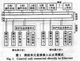
This is an IEC standard network architecture. The station control layer can use 100 Mbit/s fast switched dual Ethernet (I network, II network). Its characteristics are as follows:
1 Because the station-level and bay-level devices share the Ethernet, the entire station-based error blocking function based on Ethernet is easy to implement.
2 The measurement and control unit is directly connected to Ethernet. In the larger EHV station, the number of nodes on the Ethernet network will reach more than 50. In the event of a system failure, the data traffic on the Internet will suddenly increase, which will result in a drop in Ethernet efficiency and may cause data. Lost, and this way has no successful operation experience in domestic large-scale 500kV substations.
3 The station control layer and the bay layer use optical fiber communication, so each relay chamber needs to be equipped with 2 sets of Ethernet switches or hubs to connect the monitoring and protection unit that needs to access the Internet in the small room. The hub or switch in the small room uses AC power. The small room should introduce AC power or configure the inverter power supply (in the small room, the monitoring and protection devices are usually two DC inputs). 4 For protection devices that cannot be accessed directly on the Internet, a special protection information collection device must be set up in each cell to communicate with various types of protection devices from various manufacturers, and protect the information acquisition device to access the automation system Ethernet (1 network, II). The network), considering the large amount of information recorded on the wave, cannot share the channel with the monitoring real-time data, so the recording data needs to be networked separately or directly dialed by telephone dialing [2].
The second network architecture model is shown in Figure 2. This is a typical network structure of the current domestic EHV station automation system. The difference from the structure of Figure 1 is that each cell is provided with 2 sets of DPUs. The measurement and control units and protection units in the cell (except the recording device) are connected to the automation system Ethernet via DPU (I-network, II-network). Spacer devices use dual fieldbus networks such as LON or CAN networks. This structure has the following characteristics:
1DPU adopts embedded industrial control machine, can use DC power supply, its reliability is better than Ethernet hub or switch, and DPU has processing ability, can preprocess the data sent by the interval layer measurement and control unit to reduce the host or operator station The load, and can reduce the number of nodes on the Ethernet, improve network efficiency.
2 In addition to the anti-misoperation locking of the station control layer, the anti-misoperation logic of all equipments of this room is configured in the DPU so that even if the station control station or the host/operator station does not work, the DPU can perform anti-misoperation judgment. Blocking misuse.
3 Space layer equipment uses dual Lonwork network, although the anti-interference ability is better than that of industrial Ethernet, but due to the addition of a layer of DPU processing, the data transmission speed is slower than the first network structure, but it can still meet the real-time requirements of data [3 ].
4 Wave recording device is transmitted separately or via telephone dialing. 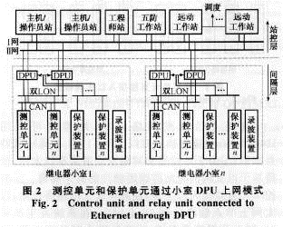
2 Establishment of EHV substation protection failure information management sub-station system From the network structure of the two hierarchical distributed automation systems mentioned above, the station-based microcomputer protection equipment (except the fault recorder device) has been connected through communication. Into the automation system, but due to the limited information provided by various types of currently protected communication protocols that are not uniform or protected, they cannot meet the requirements of scheduling and relay protection, or some protection can only provide a single communication port. In view of this, this paper proposes A platform that uses the existing ultra-high voltage substation automation system is used to construct the station protection failure information management substation system for the two kinds of network structures, as shown in FIG. 3 and FIG. 4 . 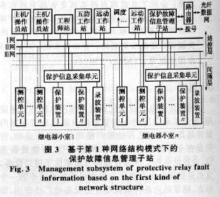

3 Conclusion At present, the hierarchical distributed architecture of domestic EHV substations provides an extremely open platform for the establishment of protection fault information management substations. The close connection between the relay protection and automation majors has formed a mutual penetration between the majors. System engineering makes it an important part of grid automation. The method for establishing the protection fault information management substation based on the EHV substation automation system proposed in this paper is to make full use of network communication technology, fully integrate the protection and automation professional within the station, and play its role more economically and rationally. The establishment of such protection fault information management substation system will inevitably provide necessary and sufficient conditions for grid fault analysis and processing.